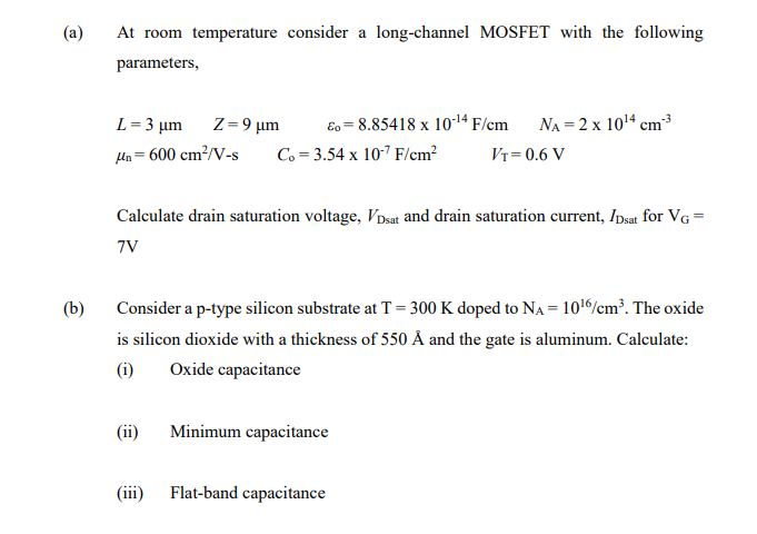
Ment mode MOSFET, one that is only “on” with a channel present when the magnitude of the gate voltage exceeds a critical value known as the threshold voltage. 2.2 The n-channel silicon MOSFET. Left: The circuit schematic of an enhancement mode MOSFET showing the. 6 mosfet operation ids vs. Vds (saturation) description – ids vs. Vds, vary vgs. as vgs incr, r decr. vdsat, where pinchoff occurs. vgd=vt pinchoff – transconductance parm. k pn =m n c ox =m n e ox /t ox 120ua/v2. k pp =m p c ox =m p e ox /t ox 40ua/v2 – mobility differences. MOSFET Operation Regions Drain end inversion charge decreases to 'zero' or VGD is just equal to threshold voltage (VTN) VGD = VGS-VDS VGD = VTN So MOSFET is in linear operation region when 0 VDS.
7.4. Overview


A thorough treatment of MOSFETs can be found in Chapter 4 of the ELEC 2210 textbook,Microelectronics Circuit Design by R.C. Jaeger.
7.4.1. Transistor Characteristics
In this lab, we will first measure the I-V characteristics of MOSFETs,including:
- Ids-Vgs in a saturation byconnection configuration, e.g.with gate tied to the drain, from which we candetermine threshold voltage.
- Ids-Vds curves for multiple gate-to-source voltages (Vgs), from whichwe can observe linear and saturation operation regions.
Using measured threshold voltage and Ids-Vds curves, we can thencheck how well first-order MOSFET theory holds up in real devices andget a practical feel of the limitation of first-order theoretical MOSFETequation.
The MOSFETs we will use in this experiment are from ALD1105, an ICcontaining two n-MOSFETs and two p-MOSFETs.A circuit symbol description of the two pairs of transistorsfrom the data sheet is shown below in figure 1.
Figure 1: Circuit Symbol and Pin Numbers for the Pairs of N-channel and P-channel MOSFETs.
Note each transistor has four terminals: drain (D), source (S), gate (G), and substrate, which iscalled body (B) in our text.As we learned in class, all the n-MOSFETs on an IC share the same p-type body, whichneeds to be tied to the lowest voltage in a system to keep all the source/drain to body PN junctions zero or reverse biased.
Similarly, all the p-MOSFETs on an IC share the same n-type body, which needs tobe tied to the highest voltage in a system to keep all the source/drain to body PN junctionszero or reverse biased.
The pin diagram seen in figure 2 shows the package layout and various pin connections for ALD1105.
7.4.2. CMOS Inverter
Premiere elements price. MOSFETs are mostly used in CMOS circuits.There are many advantages of CMOS, with the biggest beingzero standby power consumption, at least ideally. Elementor showcase.
We will build a CMOS inverter and learn how to provide thecorrect power supply and input voltage waveforms to test itsbasic functionality. For a given supply VDD, your voltage low shouldbe zero, and voltage high should be VDD.
By default, the function generator gives an output that variesfrom -VPP/2 to +VPP/2, with VPP being peak-to-peak voltage.For a square wave, the voltage low is -VPP/2, voltage high is+VPP/2. You can set the DC offset to VPP/2 to make voltage low 0.
Mosfet Vdsat Equation
We will build complexCMOS logic gates and sequential CMOS circuits from scratch usingtransistors in other labs.
